A tessellation refers to a uniform tiling of a plane with polygons, such that an equal number of identical polygons meet at each vertex. For example, the tiles in a bathroom, the squares of linoleum on an office floor, or the honeycomb pattern in a bees’ nest are all tessellations of the Euclidean plane.
 However, tessellations are also possible on non-Euclidean spaces, such as the elliptic plane (like the stitching pattern on a soccer ball), and the hyperbolic plane (like… nothing you’d find around the house). In fact, the Euclidean plane has only three regular tessellations (with squares, hexagons, and triangles), while the hyperbolic plane can be tessellated in infinitely many ways.
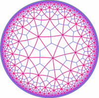
Since we do not exist in hyperbolic space, we cannot truly “see” hyperbolic tessellations. We can only “represent” them in Euclidean form. A common way of doing this is on the Poincaré disk, which is a finite circle that represents the boundary of the (infinite) hyperbolic plane that is contained inside. The image on the right is a hyperbolic tessellation drawn on the Poincaré disk.
Since tessellations of the hyperbolic plane are especially interesting and mesmerizing to look at, I wrote a small program that generates them, with a great deal of configurable options.
Using the Program
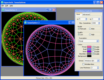
The program allows you to create an unlimited number of tessellations by selecting “File -> New” from the menu.
When viewing a tessellation, click-and-drag inside of it to shift its position within hyperbolic space. You can also click-and drag with the right mouse button to manipulate the truncation of the tessellation.
 The “Tessellation Controls” window allows you to change the settings for the tessellation that is currently active.
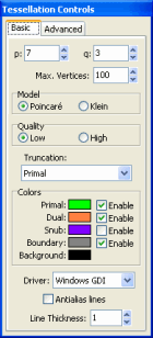
- p and q — The numbers specified by p and q refer to the Schläfli symbol {p,q} of the tessellation. The Schläfli symbol is a simple way of classifying tessellations where p is the number of sides in each polygon, and q is the number of polygons that meet at each vertex.
- Max. Vertices — This specifies the number of vertices that will be drawn (how far the tessellation will extend towards the disk boundary). More vertices will take exponentially longer to draw. Also, with more vertices, clicking-and-dragging the tessellation will become slower. With a good screen resolution, 10000 vertices fills up the Poincaré disk almost completely.
- Model — Select “Poincaré” to draw the tessellation on a Poincaré-style disk, and “Klein” to draw on a Klein-style disk. The Klein disk is similar to the Poincaré disk, except the Klein disk transforms hyperbolic space so that a line between two points appears as a straight line, instead of a circle arc, which is what the Poincaré disk gives.
- Quality — Select “Low” to display simple straight lines between vertices (and let the tessellation be drawn much faster). Select “High” to draw actual curved lines between vertices. This will slow down drawing considerably.
- Truncation — This is a list of predefined levels of truncation for the tessellation. Select from this list to apply a certain truncation. You can also do free-form truncation by clicking-and-dragging on the tessellation with the right mouse button.
- Colors — This allows you to select different colors for each of the components of the tessellation, and to enable or disable drawing of each component.
- Driver — This selects what functions the program will use to draw the tessellation. Select “OpenGL” to use OpenGL technology, or “Windows GDI” to use plain Windows functions. In most cases, selecting OpenGL will enable the images to be drawn considerably faster, especially with Antialiasing enabled. However, OpenGL is not supported on some (very) old graphics cards. Also, if you create multiple tessellations, only one can be drawn with OpenGL at any given time.
- Antialias lines — Check this box to draw “smooth” lines.
- Line Thickness — This specifies the thickness (in pixels) of the lines that make up the tessellation.
- Advanced — These options are mostly experimental and will not be discussed here.
Gallery
Here’s a brief collection of images created using this program. Click on an image to view a larger version.
none, (0,1,0), (0,.5,.5), runcinated, omnitruncated, and snub.

 truncation")
 truncation")


Links
- This program borrows a substantial amount of code from Don Hatch‘s page, which has an exhaustive gallery of {p,q} permutations and truncations, as well as a tessellation Java applet.
- David E. Joyce’s tessellation page at Clark University.
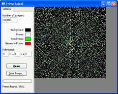
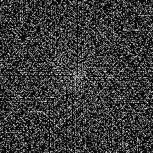
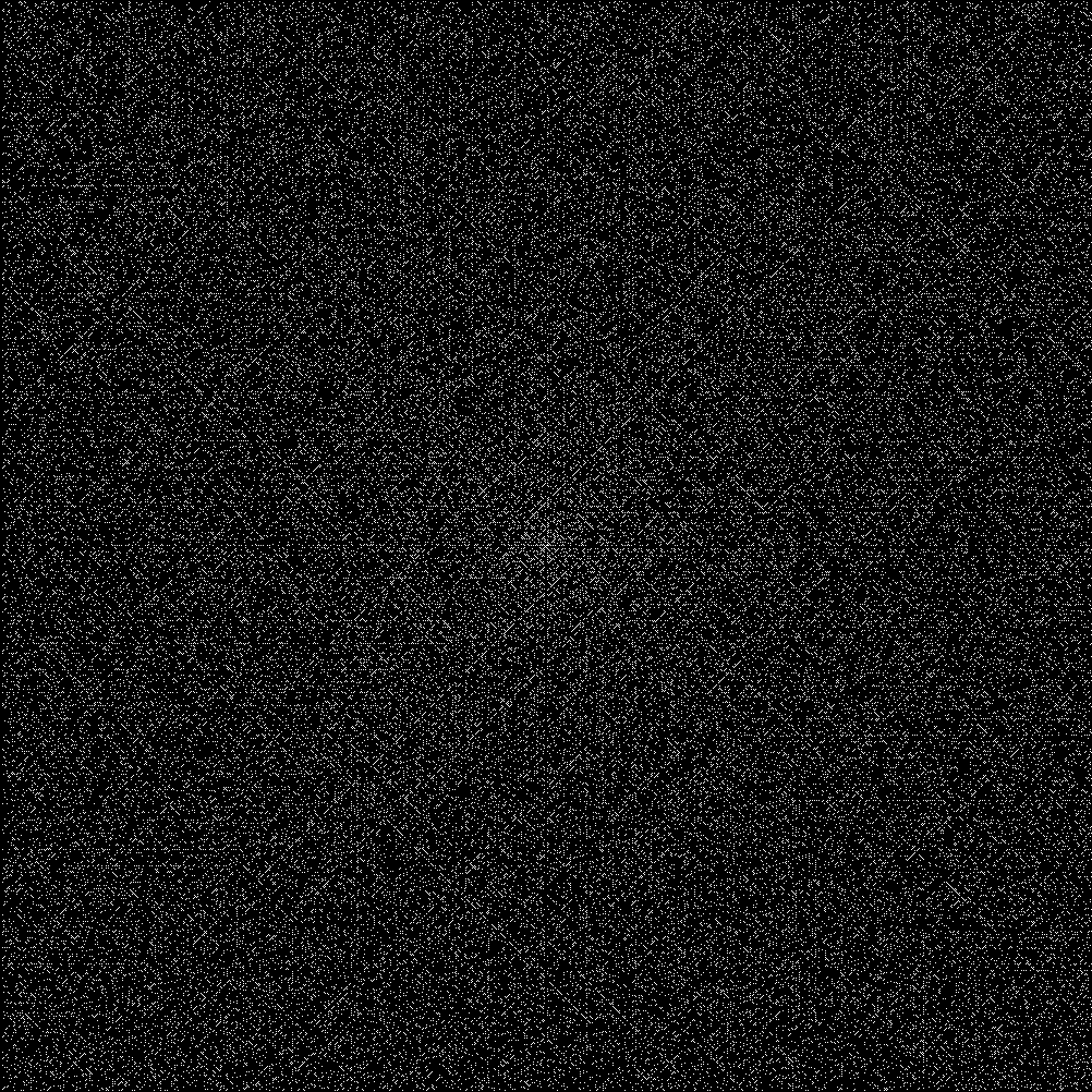
 However, prime numbers do exhibit a curious
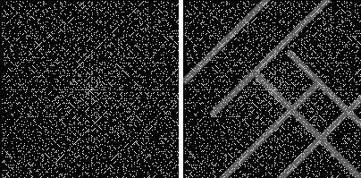

