These are very rough beginners’ notes for dealing with inexpensive microcontroller boards, and some of their peripherals. These were the result of a random shopping spree on AliExpress, and I haven’t used all of them in home projects yet, but it’s nice to know they’re readily available and very cheap to replace if necessary.
As an aside, part of the fun of dealing with these cheap components is the process of figuring out how they work (since the documentation from the manufacturer is often lacking), and working around any quirks found along the way. A big help in this process, and another part of the fun, is reading the reviews on AliExpress, which often contain valuable insights from other users who have gone through the trouble of getting them working.
ESP8266 board with 0.96″ OLED display “HW-364A”
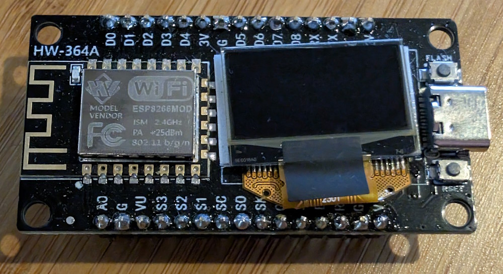
- Flash with esptool (micropython)
- Onboard display: 128×64, I2C (SCL: 12, SDA: 14), address 0x3C (The topmost 16 rows of pixels are yellow, the rest are blue)
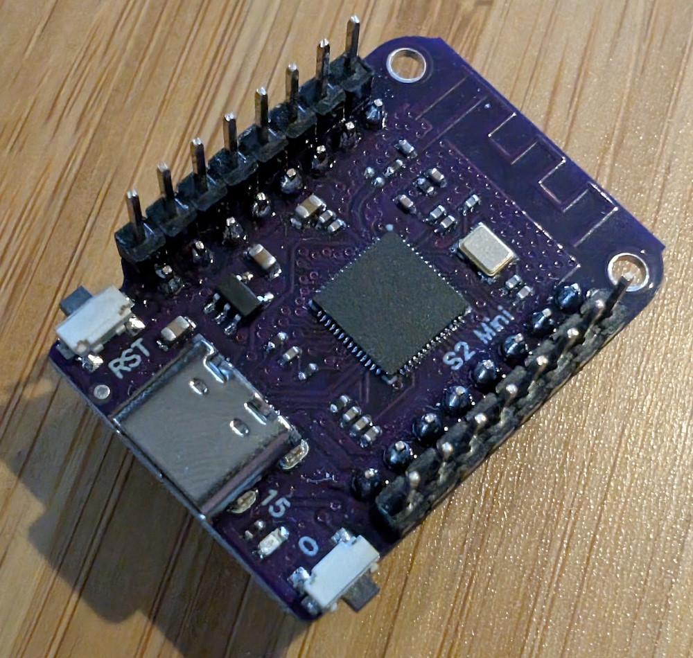
ESP32-S2 “Mini”
- Actual documentation!
- Flash with esptool (micropython)
- Onboard LED: GPIO 15
- Onboard button: GPIO 0 (hold down when powering-up for flash mode)
- Note: This arrived in a weird state that was unrecognizable by my PC, and when I put it in flash mode, it kept resetting every few seconds. To erase the flash, I had to connect it in flash mode and immediately run the esptool command to catch it before it reset again.
- For working in Arduino IDE: select “LOLIN S2 Mini”; can only be flashed by putting it in flash mode (press Reset while also pressing 0).
ESP32-C3 “Super Mini”
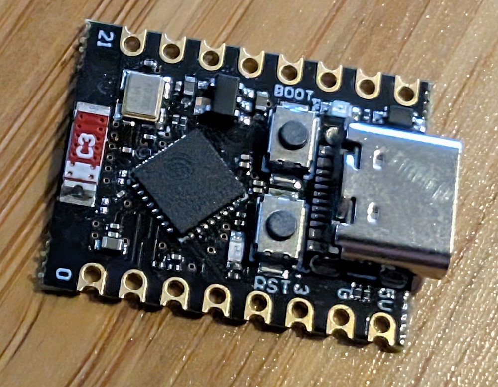
- Flash with esptool (micropython)
- Onboard LED: GPIO 8
Untitled ESP32-C3 board with 0.42″ OLED display
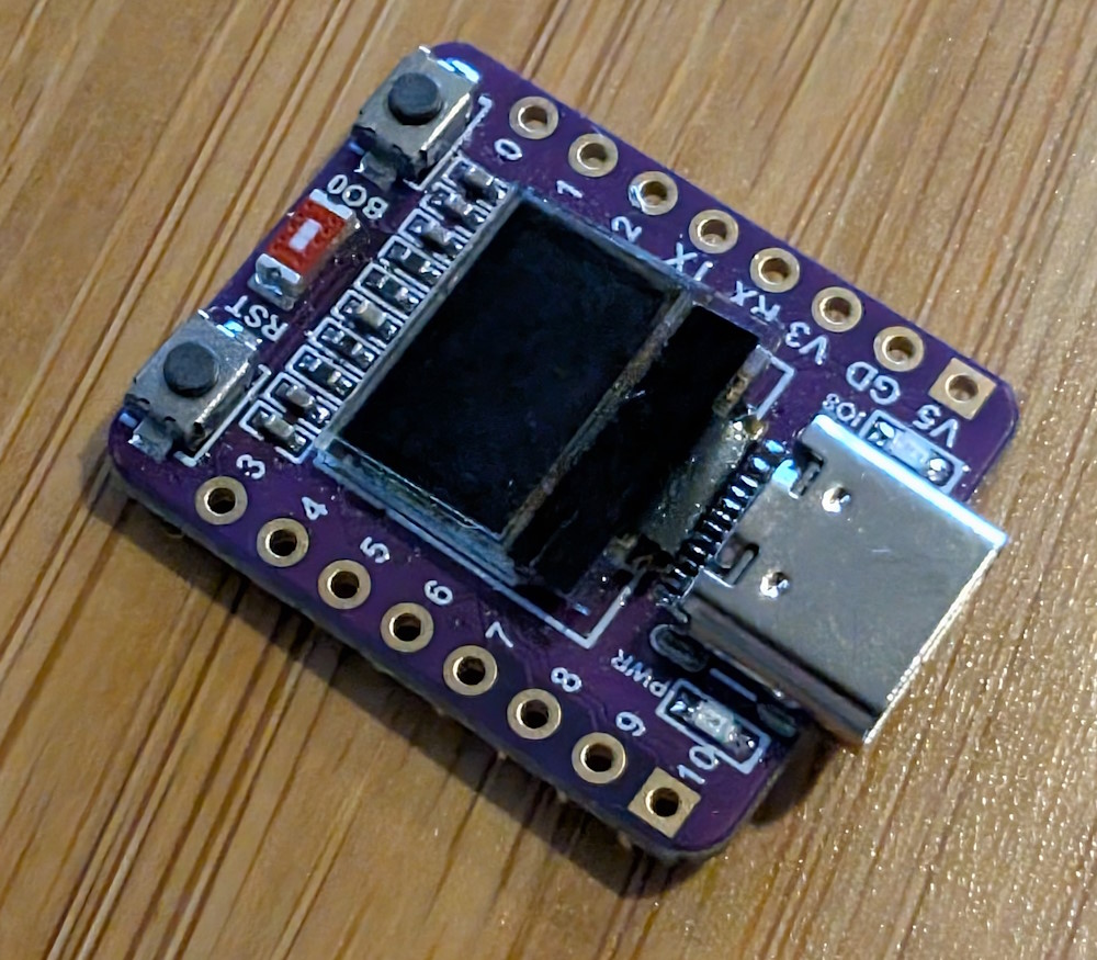
- Onboard display (the cutest thing ever): 72×40, I2C (SCL: 5, SDA: 6)
- Onboard LED: GPIO 8
- Note: The display on this board seems to work better with Arduino IDE (select “ESP32C3 Dev Module”) rather than MicroPython. Use the
u8g2library to control the display.
ESP32-S3 “Super Mini”
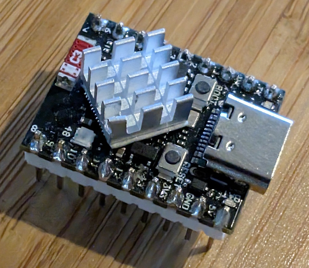
- Flash with esptool (micropython)
- Onboard RGB LED (NeoPixel): GPIO 48
- Also a regular LED: GPIO 48
- Threw a heatsink on it, because why not.
Untitled RP2040 board #1
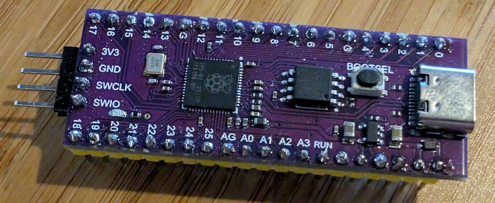
- Flash MicroPython directly from Thonny
- Onboard LED: GPIO 25
RP2040 board “YD-RP2040”, V1103/1084
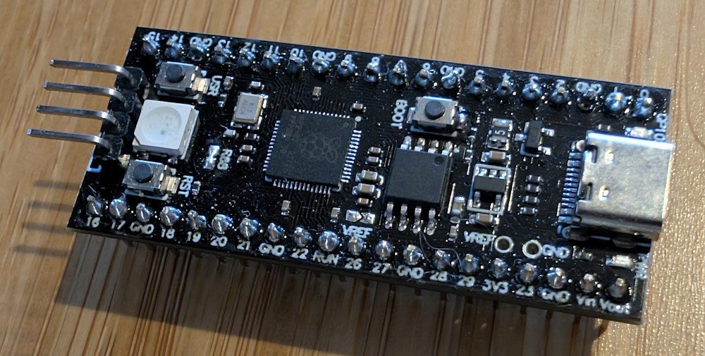
- Flash MicroPython directly from Thonny
- Onboard RGB LED (NeoPixel): GPIO 23
- Note: to enable the NeoPixel, close the solder bridge labeled “RGB”, although on my board it was labeled “R58” (a worthy attempt at spelling “RGB” by a non-English speaker). If the solder bridge is left open, then GPIO 23 can be used as regular I/O.
- Onboard user button: GPIO 24
- Note: when initializing this pin for input, remember to enable the internal pull-up resistor:
usrButton = machine.Pin(24, machine.Pin.IN, machine.Pin.PULL_UP)
- Note: when initializing this pin for input, remember to enable the internal pull-up resistor:
- Another onboard LED: GPIO 25
RP2040 board “ProMicro”
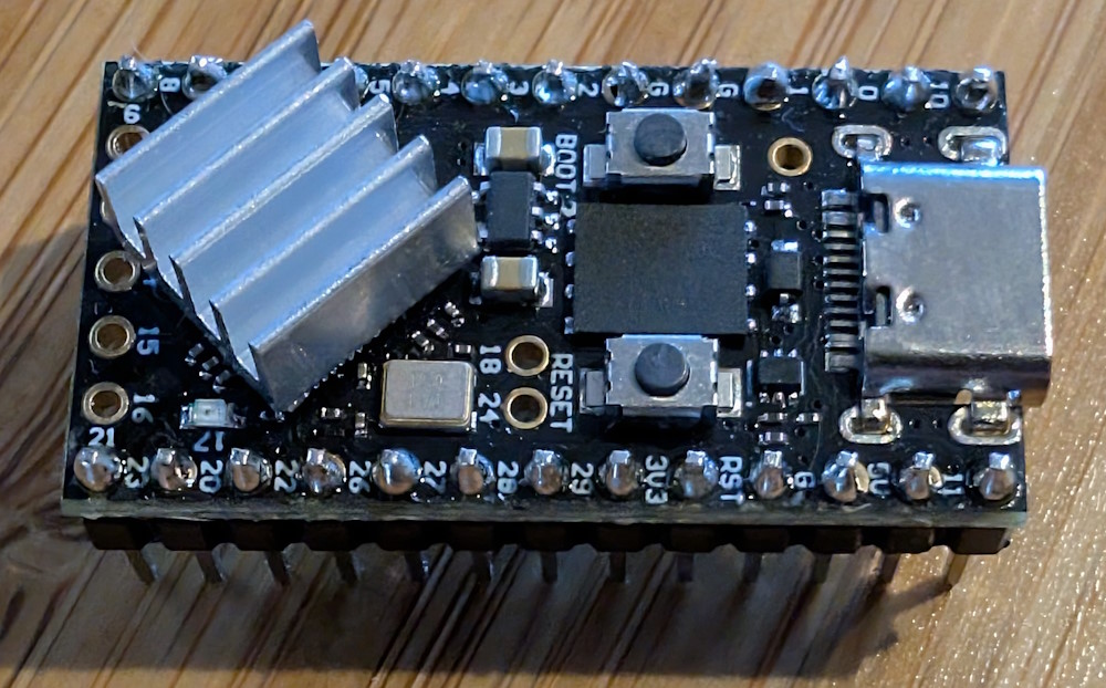
- Flash MicroPython directly from Thonny
- Onboard LED: GPIO 17
RP2040 board “RP2040-Zero”, V1083
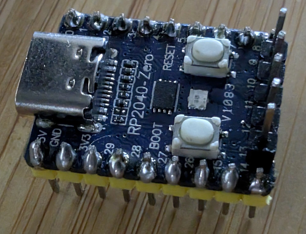
- Flash MicroPython directly from Thonny
- Onboard RGB LED (NeoPixel): GPIO 16
Doing stuff
Refer to MicroPython documentation!